


MOLCAS manual: Next: 8.20 GRID_IT Up: 8. Programs Previous: 8.18 genano
|
 |
(8.7) |
 |
(8.8) |
8.19.1.1 Creating the z-matrix
The z-matrix is created by choosing the first atom in the xyz-file and put that
in top of the z-matrix file (the example is a methane dimer:
H
The next atom is chosen as the closest atom not already in the z-matrix and in
the same fragment
as the first. The distance to the closest neighbor within the z-matrix is
calculated and written into the zmatrix:
C
H 1.104408 0 1
The number zero means "do not optimize" and is appended to all coordinates
within fragments and the 1 at the right hand side keeps track of which
atom that were the closest neighbour. The next molecule is again chosen
as the one not in the z-matrix but in the fragment. The distance between
the third atom and its closest neighbour and the angle between the third
atom, the closest atom and the second closest atom with the second closest
in the middle is added.
C
H 1.104408 0 1
H 1.104438 0 109.278819 0 1 2
For the fourth atom a dihedral angle is added and after that all remaining atoms
only have coordinates related to three neighbors. When all the molecule in the
fragment has entered the z-matrix the closest atom in another fragment is taken
as the next atom. Neighbors to atoms in that fragment is chosen from the same
fragment if possible and then from the previous fragment. When two atoms from
the second fragment has been added the z-matrix looks like this:
C
H 1.104408 0 1
H 1.104438 0 109.278819 0 1 2
H 1.104456 0 109.279688 0 -119.533195 0 1 2 3
H 1.104831 0 109.663377 0 120.232913 0 1 2 3
H 3.550214 1 75.534230 1 -133.506752 1 3 4 1
C 1.104404 0 78.859588 1 -146.087839 1 7 3 3
Note that coordinates linking fragments have a 1 after and will be optimized
and that the last carbon has one neighbor within its own fragment and two
within the previous fragment.
There are two special exceptions to the rules described above. Firstly, if it is possible neighboring atoms are chosen from non-hydrogen atoms. (When linking an atom to neighbors, not when choosing the next line in the z-matrix.) Secondly, dihedral angles are rejected if the angles between the three first or the three last atoms are smaller than 3 degrees since very small angles makes the dihedral ill-defined.
8.19.2 Dependencies
The GEO program requires that gateway have been run with either the keyword geo or hyper to setup internal communication files.
8.19.3 Files
8.19.3.1 Input files
Apart from the standard file Geo will use the following input files.| File | Contents |
| RUNFILE | File for communication of auxiliary information. |
8.19.3.2 Geo communication files
When the emil command > DO GEO or the keywords zonl or zcon are used a directory $GeoDir is created (by default in the input-directory: $CurrDir/$Project.Geo). This directory is used to store files related to geometry optimization and z-matrix generation.
| File | Contents |
| $project.zmt | The file with the z-matrix as described above.
|
| general.info | A file used for storing general info about the geometry optimization, it is human readable with labels. The file is automatically setup by the program.
example:
|
| disp????.info |
A file that contains all displaced coordinates. A new instance of the file is created automatically for each geometry step.
|
| $project.disp????.energy | A one line file that simply state the current energy for the displacement. If several energies are calculated this will first contain a scf energy and is then updated with the mp2 value when that calculation is finished. The file is written by a small addition to the add-info files and currently collects energies from scf, mp2, rasscf, caspt2, chcc, cht3, and ccsdt. If it should be used with new energy relaxation methods this must be added manually.
|
| $project.final????.xyz | An xyz-file with coordinates for all fragments after XXXX geometry optimizations. This is just for the benefit of the user and should probably be replaced with the same output as created by slapaf, opt.xyz-file for optimized geometry and molden-file for history. Some internal history would still be needed for building more advanced geometry optimization algorithms and convergence criteria though.
|
| $project.geo.molden | A molden file with information about the geometry optimization. The file could be browsed in molden or LUSCUS. The last energy-value is set to zero since the file cannot be created after the last energy calculation and need to be inserted by the user. |
8.19.4 input
The general input structure of a geo-calculation looks like this:
&Gateway
[keywords to modify fragment position (frgm,origin)]
coord=fragment1.xyz
...
coord=fragmentN.xyz
[regular keywords + keywords to modify ]
>> DO GEO
&Seward
[energy relaxation methods with any of their keywords]
>> END DO
Both the keywords used to translate and rotate xyz-files (frgm and origin) and the keyword to modify the behaviour of the optimization (hyper, and oldz) is described in more details in the gateway section of the manual.
Here is an example input to calculate the relative orientation of two methane
molecules:
>> export GeoDir=$CurrDir/$Project.GEO
&Gateway
Coord=$MOLCAS/Coord/Methane1.xyz
Coord=$MOLCAS/Coord/Methane2.xyz
Group=c1
basis=aug-cc-pVDZ
hyper
0.15 2.5 2.5
>> Do Geo
&Seward
CHOLESKY HIGH
&SCF
&MP2
>> End Do
In order to run the job above in a task-farm parallel mode,
one just needs to slightly modify the original input:
*activating an TaskFarm's interface in GEO/HYPER
>> export MOLCAS_TASK_INPUT=NEW
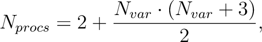
*specifying number of cores/cpus available for parallel execution
>> export MOLCAS_NPROCS=2
>> export GeoDir=$CurrDir/$Project.GEO
&Gateway
Coord=$MOLCAS/Coord/Methane1.xyz
Coord=$MOLCAS/Coord/Methane2.xyz
Group=c1
basis=aug-cc-pVDZ
hyper
0.15 2.5 2.5
>> Do Geo
&Seward
CHOLESKY HIGH
&SCF
&MP2
>> End Do
*setting the TaskMode's execution model to MPP
*each energy/displacement is computed in paralel
*by using 2 cores
>>> EXPORT MOLCAS_TASKMODE=1
*actual execution of TaskFarm via EMIL
>>> UNIX SERIAL $MOLCAS/sbin/taskfarm
Next: 8.20 GRID_IT Up: 8. Programs Previous: 8.18 genano